


WHITE PAPER
Understanding The Influence of Belt Furnace and Firing parameters on Efficiency of Silicon Solar Cells

Abstract
Silicon solar cells are one of the most widely used and highly efficient photovoltaics. With growing competition from second and third generation photovoltaic��s and decreasing module prices, there is an increasing demand for improving efficiency and decreasing the cost of silicon solar cells. Screen printed metallization, which is one of the most widely used contact formation methods, has been reported as having a significant impact in determining the efficiency of the solar cell. This effort will summarize the influence of firing process of screen-printed contacts and belt furnace parameters on the efficiency of silicon solar cell.
Introduction
The metallization contact formation is an important step in determining the efficiency of the solar cell. The common metallization processes include photolithography, buried contact technology and screen-printing. The photolithography process involves selectively etching patterns of thin film material onto a silicon substrate. Photolithography is widely used in laboratories and it produces highly efficient solar cells. However, this method is both time consuming and resource intensive which limits it to laboratory research. The more efficient metallization contact formation method is the buried contact method. In this method, grooves are scribed onto the silicon wafer by using mechanical or laser methods and then copper is plated into the holes. The contact metallization is achieved through electro less plating of Ni/Cu followed by sintering. The better aspect ratio obtained from the grooving helps with increasing the efficiency of the solar cell. The third and most commonly used method in commercial production is the screen-printing method. Screen-printing is a cost effective method that uses a screen and squeegee to print the metallization paste onto the substrate; which is then fired for contact formation. This work will focus on summarizing the ideal screen printing and firing process parameters and their impact on cell efficiency.
Screen Printing
The screen-printing method consists of a thick film metal paste that is composed of metal powder, glass fritt, solvent and non-volatile polymers that are blended together in a three roll mill. A squeegee applies a downward force on the paste moving it across the screen that has a deposition pattern within. This action creates a reduction in viscosity of the paste so it can penetrate into the screen holes. This way, the metal paste is deposited in select patterns onto the substrate. The factors that affect the screen-printing process include snap off distance, squeegee pressure and squeegee speed.
The snap off distance is the distance between the screen and the wafer. During the printing process, when the paste is printed onto the screen, a downward force is applied to the screen. The screen, being elastic, restores its shape and this upward movement aids in the deposition of the paste. If the snap off distance was too high, then pressure will have to be applied to force the paste onto the wafer. If it is too low, the paste might not get released from the screen. The pressure applied also plays an important role in the deposition of the paste. When too much pressure is applied, excessive paste from the screen could be deposited which can break the wafer. On the contrary, when too little pressure is applied, the paste might not get released from the screen at all. The speed of the squeegee movement also determines the print quality. If the speed is too high, the paste can miss many holes and lead to a non-uniform deposition.
Firing
The firing process, also referred to as sintering, is one of the key steps with which the front-metal contact is formed in a silicon solar cell. In this process, the thick film paste is dried at about 150oC to remove much of the solvents. The presence of solvents can cause excessive out gassing which can lead to cracks and voids. The dried substrates are then fired inside a firing furnace. The firing process consists of four primaries. The first step is the initial temperature ramp up where the paste solvents are volatilized. The second step is the burn out. The objective of the burn out phase is to remove all of the organic binder that was used in paste formation. The burn out phase is carried out at 300-4000C. The third step is the sintering, or the firing process, which is done between the ranges of 700-800C. During this process, the Ag metal forms a bond with the underlying silicon substrate to form metal contact. The final step in the firing process is the wafer cool down phase.
The mechanism behind contact formation in a fire through contact is very complex and not fully understood [4]. According to Mohammed Et al, the process starts by evaporating the solvent between 100-200C and then burning out the polymer between 200 and 400C. Later, from 400-600C, the glass frit melts and the sintering of the Ag particles take place. Furthermore, from 600-800C, molten glass with some amount of dissolved Ag etches the silicon nitride anti reflection coating and then reaches the Si surface. Here, it reacts and etches a very thin layer of Si. Ag in the glass will then precipitate onto the Si surface in the form of crystallites. An ideal temperature profile for the firing process is illustrated in Figure 1.
The quality of the contact influences the shunt resistance, series resistance and junction leakage current, which have a significant impact on the efficiency of the solar cell. Hence, it is very important to understand various aspects of the firing process to be able to achieve higher efficiencies. Some of them include; peak temperature, dwell time, and the temperature at which Si �CAg alloy formation happens.

Figure 1: Ideal temperature profile for Contact firing [1]
Effect of Peak Temperature
The peak temperature of the sintering process is observed as having a significant impact in determining the efficiency of the silicon solar cell. Studies by Carroll et al have reported a direct correlation between peak temperature and cell efficiency. The results from this study have shown that the ideal peak temperature range for metallization firing is 780-800 oC. Cheng et al has also studied the effects of various peak temperatures on the efficiency of solar cells and has confirmed the same results. The study observed that when the silicon solar cells are under fire, one half of the cells display high contact resistance while the other half displays low contact resistance. At the same time, when the solar cells are fired within the optimum range of 780-800 oC, the contact resistance has been reported as being uniform throughout the entire cell at higher efficiency. However, when the solar cells were over fired, there was an overall decrease in efficiency due to shunting. An investigation by Hilai et al has demonstrated similar phenomena. At lower temperatures, the distribution of Ag was irregular and the contact formed was very small with high specific contact resistance. However, at high temperatures, the excessive shunting resulted in a decrease in efficiency. Thus, from the results of the above studies, it can be observed that the peak firing temperature has an important role in determining the efficiency of the silicon solar cells.
Effect of Soak Time
Soak time refers to the time at which the substrates with metallization printed on them are held at peak temperature. The soak time is an important parameter in determining the cell efficiency because the diffusion of silicon and silver is a function of time and temperature. Research done by Lee et al, Cooper et al, and Hilai et al have demonstrated the effects of soak time on the efficiency of the solar cell. From the results in the published literature, it is understood that there is a significant interaction between soak time and peak temperature. The highest efficiencies have always been reported for shorter soak time. It has been reported that increasing the soak time will increase the contact resistance. A study, done by Cooper et al, of the interface and bulk metallurgies of the contact, has demonstrated an increase in the thickness of the interfacial glass layer with an increase in soak time. The thicker contact layer results in an increase of contact resistance.
Belt Furnace Parameters
Apart from the firing conditions, studies have reported a correlation between the furnace parameters and the efficiency of the solar cell. Edward Bruce has done studies on the influence of belt furnace parameters and solar cell efficiency. He observed that the cleanliness of the furnace has a significant impact on cell efficiency. The common source for furnace impurities include carbon residue, impurities from air inlet, foreign materials picked up by the conveyor due to contact, etc. Solar cells that were fired immediately after cleaning the furnace have been reported as being more efficient than their counterparts that had been fired on a furnace with impurities. The thickness of the oxide layer has also been reported as having a significant impact on cell efficiency. The oxide layer thickness can be controlled, as well, by controlling the atmosphere inside of the muffle. Hilai et al has reported an increase in the conductivity of the silicon solar cell fired within a reduced atmosphere with a small percentage of Hydrogen. The substrate carrier boat has been reported as having very little impact in determining cell efficiency. Results from Bruce et al studies have shown no significant impact in efficiency for directly placing the silicon substrate onto the nichrome belt and firing them on a quart carrier.
Furnace for Firing Operation
The HSH series furnace is a specially designed infrared furnace that caters to the needs of the photovoltaic metallization firing requirements. The heating in this furnace is achieved with the help of short wave infrared lamp heaters. The fast response of the IR lamps allow for quick heating. The furnace is rated at 1000 oC and can operate very well in the 750-800 oC range required for sintering of front contact metallization. The belt width comes in various standard sizes, including, 250mm, 300mm and 380mm to match with the requirements of the wafer size. Cooling can be achieved through forced air, as well as, water per requirement. The presence of a muffle helps to control the atmosphere within the furnace, as well as, prevent the external atmosphere from entering. In short, the muffle design helps maintain a cleaner furnace atmosphere. As a standard feature, this furnace is equipped with a steel brush and helps in the cleaning process of the conveyor belt. Ultrasonic belt cleaning is available as an extra option as well.
A microprocessor based PID controller controls the furnace. Type K thermo-couples are used for determining the zone temperatures. Controls are located on the right hand side and can be viewed from the entrance of the furnace. The central processing unit (CPU) is mounted under the exit table. The furnace is controlled by a microprocessor based controller system and the CPU is loaded with a Windows operating system that allows for easy computing. The computer system comes with a pre-installed program for controlling the Confurnace parameters including the belt speed and the zone temperatures. Temperature profiles can be stored and retrieved for future purposes. Thermocouple ports are located at the entrance table for connecting the profiling thermocouple directly to the microprocessor. This feature allows the monitoring and recording of the actual temperature experienced by the part. Software is also provided with the computer to capture, display, printout and store the furnace profile. The furnace is equipped with a redundant overheat safety protection system which incorporates an additional type ��K�� thermocouple in the center of each controlled zone and the multi-loop alarm.
Detailed specification for a HSH2503-0509 furnace is available in Table 1.
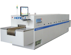
Figure 2: HSH2503-0509 Firing Furnace
| Specification | HSH2503-0509 |
|---|---|
| Rate Temperature | 900 deg. C max Normal operating: 850 deg C |
| Belt Width | 10�� (250mm) |
| Effective Above Belt Clearance | 0.035�� (9mm) |
| Control Zones | 5 |
| Conveyor Speed | 28-140 IPM (700-3,500mm/min) |
| Muffle opening size | 11�� x 1.2�� (WxH) 280mm x 30 mm (W x H) |
| Loading Table | 18�� x 33�� (LXH) 450mm x 850mm (LXH) |
| Unloading Table | 22�� x 33�� (LXH) 550mm x 850mm (LXH) |
| Belt | Balanced V Weave, Cr20Ni80 |
| Heating Elements | Short Wave IR Lamps |
| Insulation | High quality ceramic fiber |
| Temperature Controller | Intelligent PID Shimaden Controller |
| Alarm | Thermocouple, Over Temp, Belt Stop. Audio and Visual Alarm |
| Atmosphere | 4 pipes of dry clean air or N 2. 2-6 m 3/h, 1.1-3.3 CFM |
| Cooling | 2 stage water cooling. 2-3 m 3/h, incoming water at 10 C or colder |
| Across Belt Temperature Uniformity | +/- 4 deg C |
| Overall System Width | 40�� (1,000mm) |
| Overall System Length | 14�� / 168�� / 4,290mm |
| Overall System Height | 52�� (1,316mm) |
| Net Weight | 1,760 lb (800kg) |
| Power | Three-phase, 480VAC, 60Hz, 38 KVA Max Normal operating power draw is about 15 KVA |
Table 1: Specifications of HSH2503-0509 Firing Furnace
Conclusion
The firing process is a very important step in determining the efficiency of the silicon solar cell. The peak temperature of the firing, the soak time and the furnace design itself has a significant influence on the efficiency of the silicon solar cell. The HSH series is an IR furnace that matches well with the requirements for the firing operation.
References
Sopori, B., Mehta, V., ��Fundamental Mechanism in the Fire Through Contact Metallization of Silicon Solar Cells: A Review��, 17 th Workshop on Crystalline Silicon Solar Cells and Modules: Materials and Processes, Aug 508, 2007.
Cooper, I, B., Ebong, A., ��Understanding and Use of IR Belt Furnace for Rapid Thermal Firing of Screen-Printed Contacts to Si Solar Cells��, In IEEE Electron Device Letters, Vol.31, No.5, May 2010, pp. 461-463.
Edwards, B, M., ��Screen and Stencil Print Technologies for Industrial N-Type Silicon Solar Cells��, PhD Thesis, University of New South Wales, Australia.
Hilali, M, M., Al-Jasim, M, M., ��Understanding the Formation and Temperature Dependence of Thick-Film Ag Contacts on High-Sheet-Resistance Si Emitters for Solar Cells �� in The Journal of Electrochemical society , Vol. 152, No.10, 2005, pp. 742-749.
Hoornstra, J., Heurtault, B., ��Stencil Print Applications and Progres For Crystalline Solar Cells�� In 24th European Photovoltaic Solar Energy Conference and Exhibition, 21-25 September 2009, Hamburg, Germany.
Hilali, M., ��Understanding and development of manufacturable screen printed contacts on high sheet resistance emitters for low cost silicon solar cells��, PhD dissertation, Georgia Institute of technology.
Mihailetchi, V, D., Jourdan, J., �� Screen Printed N type Silicon Solar cells for Industrial Applications��.
Ebong,A ., Brody, J., Rohatgi, A., and T. Williams, �� Optimization of front metal contact firing scheme to achieve high fill factors on screen printed silicon solar cells��, In PVSEC 1999 Japan.