


WHITE PAPER
A Practical Guide for Improving Crystalline Solar Cell Efficiencies through
Optimization of the Firing Process
By Bjorn Dahle, KIC
The crystalline solar cell manufacturing industry has long acknowledged that when solar wafers are processed with an optimal thermal profile, the solar cell efficiency increases. Studies from Heraeus and KIC have quantified that such process optimization may lead to significant increases in cell efficiencies up to several tenths of percentage points. (Refer to the end of the article for a link to a Heraeus and KIC study.*) Because the solar cells are priced as a function of their efficiencies, the thermal process optimization potentially represents a significantly profitable endeavor.
The difficulty, however, is twofold: 1. to obtain accurate and repeatable profile readings, and 2. to identify the correct furnace recipe to achieve an optimum thermal profile.
This document focuses on the use of KIC’s new solar products (e-Clipse TC attachment fixture, SunKIC Profiler, Spectrum process optimization software) to help silicon solar cell manufacturers improve cell efficiencies while maintaining or improving productivity. The examples used come from the metallization process; however, the principals presented also are applicable for other thermal processes.
Thermal Process Development
As opposed to more mature industries such as semiconductor and electronics assembly, the solar industry currently does not have a clear understanding of the ideal wafer profile or process window for each unique application (wafer, silver paste, furnace and other variables). There may be numerous wafer properties and variables in the processes upstream from the metallization furnace that affect the ideal wafer profile. Therefore, each manufacturer must perform a design of experiment (DOE) to identify the best wafer profile or range of profiles (Process Window). Such a DOE typically involves changing the wafer profile while the cell efficiency, fill factor and other quality measurements are measured. The profile is changed numerous times (on identical wafers that have been processed up to the firing furnace) in a “trial and error” approach until the responsible engineer is satisfied with the cell efficiency.
The wafer profile itself is a result of the furnace settings and how the thermodynamic properties of the furnace heat and cool the wafer. A modern metallization (firing) furnace can be set up using tens of millions of alternative recipes (combination of zone temperatures and conveyor speed), making the DOE both difficult and time consuming. Even worse, when changing one profile parameter, e.g. the peak temperature, all the other parameters such as time above 500°C, time above 600°C, ramp rate, etc. also change. As a result, it becomes difficult to determine what caused the improvement in the cell efficiency.
Finally, the traditional methods to record the wafer profile suffer from inaccurate and non-repeatable measurements. This problem is caused by the method used to attach the thermocouples (TC) to the wafer. It is not uncommon to get a 50°C difference in peak temperature readings from one profile to the next when taken only minutes later. Clearly, a new TC attach method is required before any purposeful DOE can take place.
Trial and Error Experimentation for Improved Wafer Profiles
The following steps are recommended to explore new and improved wafer profiles that result in higher cell efficiencies:
1. KIC’s TC attachment method.
In order to significantly improve the profile measurements, KIC developed a four TC
attachment fixture called the e-Clipse. The user simply slides his or her own wafer into
the fixture and four spring loaded TCs with flattened disk beads automatically seat
themselves. The e-Clipse is both highly accurate and repeatable.
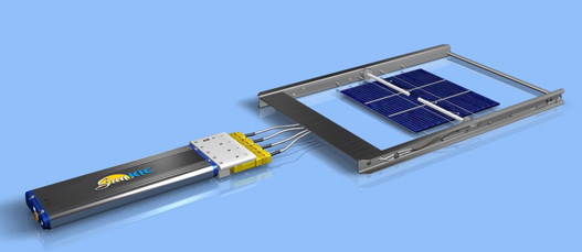
Figure 1. The e-Clipse TC attachment fixture and SunKIC profiler
2. Initial furnace setup and associated wafer profile
The starting point for the DOE is whatever furnace set points (recipe) that are currently
being used. Alternatively, the responsible engineer may use his knowledge and
experience to select the initial setup. One option for factories with multiple production
lines is to use the profile in the furnace that yields the highest cell efficiency.
When selecting a particular combination of conveyor speed and zone temperatures, the furnace recipe will yield a specific wafer profile and associated cell efficiency as depicted in Figure 2.

Figure 2. Initial furnace setup and associated profile and cell efficiency
3. Second furnace recipe
To experiment with new and improved profiles, the responsible engineer may use his or
her knowledge and information about wafer and silver paste properties, etc. to change the
profile in certain directions. (The profile data and cell efficiency numbers in this article
are only established to illustrate the process optimization method. The actual numbers
vary with each application. The temperatures used in these examples are higher than
what the industry has been used to seeing. This is a result of the more accurate
SunKIC/e-Clipse readings that record data much closer to the actual wafer temperatures).
In this example of a multi crystal wafer , let us change the peak temperature in increments of 10°C. We need to find the furnace recipe that increases the peak wafer temperature from the current 830°C to 840°C as seen in Figure 3.
The engineer will set up the furnace to the newly chosen recipe, wait for the furnace to stabilize at the new temperature(s), run one or more wafers through the furnace, and measure their average cell efficiency.

Figure 3. New furnace recipe and associated wafer profile and cell efficiency
4. Third furnace recipe
The cell efficiency increased when running the furnace at recipe 2, so let us change the
recipe again to achieve a peak temperature of 850°C (Figure 4).

Figure 4. Third recipe resulting in a profile yielding higher efficiency again.
5. Fourth furnace recipe
The cell efficiency improved (Figure 4) so let us increase the peak temperature yet again,
this time to 860°C.

Figure 5. New recipe resulting in a profile yielding lower cell efficiency
6. Fifth furnace recipe
The efficiency dropped (Figure 5). It is tempting to conclude that the previous profile
with a peak temperature of 850°C is the best. The problem with this experiment is that
although we focused on changing the peak temperature, all the other dimensions of the
profile likely changed as well. Figure 6 shows how time above 500°C and 600°C kept
changing. At this point, we do not know whether the peak temperature or time above
500°C or 600°C contributed to the changes in cell efficiency.

Figure 6. DOE where multiple profile variables changed simultaneously
7. Select furnace recipes that only change the peak profile while keeping everything else
constant
What is needed is the capability to only change one variable at the time. The KIC
Spectrum enables the user to lock in all but one parameter at a time. The engineer needs
to ask the software to identify the recipes that change the peak temperature in 10°C
increments while keeping time above 500°C and time above 600°C the same as depicted
in Figure 7. The Spectrum essentially evaluates all of the millions of alternative furnace
recipes, and it predicts the resulting wafer profile for each. It then selects the furnace
recipe that produces the requested profile. The Spectrum will provide its
recommendations within seconds of completing the profile run.
The cell efficiency changes are now a direct result of the peak temperature only. Once the highest efficiency has been found based on the peak temperature, (recipe 6 in figure 7), this dimension can be locked while changing one of the other profile parameters. This continues until the highest cell efficiency has been found.

Figure 7. New recipes increase the peak temperature on the wafer
in 10°C increments
while keeping the other profile dimensions stable.
Transferring the Process from the Pilot Line to the Production Lines
The simple but efficient process improvement guideline above will yield results quickly. Most companies will perform such work in the laboratory furnace or pilot line furnace. The next challenge is to transfer the optimum process (or profile) to the production lines (Figure 8). Because the production line furnaces are different than the furnace where the process was developed, the process transfer may be difficult. Even if the production line furnaces are of the same make and model, they will have different thermodynamic properties due to wear and tear, aging heating lamps, preventive maintenance changes, and more.

Figure 8. How to transfer the optimized process to the production lines
1. Process transfer from the Pilot furnace to the production furnaces
The solution is to enter the optimal profile into the SunKIC profiler, run a profile, and to
ask the Spectrum software to identify which setup will yield the requested profile for
each production furnace(Figures 9 and 10). Each production furnace will have different
settings, but they all will produce the same wafer profile. The Spectrum software makes
the process transfer extremely quick even when the furnaces are all different.

Figure 9. Transfer the optimized process to the first production line

Figure 10. Transfer the optimized process to all the production lines
Periodic Adjustment of the Production Furnaces to Consistently Produce Higher Efficiency Cells
The final aspect of setting up and running a solar cell firing process in the “sweet spot” of the cell efficiency is to periodically adjust the furnaces in a similar fashion to the above when the process starts drifting. The thermodynamic properties of the furnaces will change over time due to aging lamps, preventive maintenance and more. Due to the strong financial benefits of consistently producing solar cells with high efficiency, the furnaces should to be adjusted when the measured cell efficiency drops. The good news here is that the KIC Spectrum process optimization software will identify the correct furnace settings within seconds of running a profile, hence minimizing production downtime.
Conclusion
Fine tuning the firing furnace to achieve a more optimal wafer profile leads to higher cell efficiencies and, hence, higher profitability. This article demonstrates easy steps to achieve this. KIC’s SunKIC solar profiler, e-Clipe TC attachment fixture, and Spectrum process optimization software make this possible even when the ideal profile or process window is unknown. Due to the dynamic nature of the thermal process that will drift throughout the day, week and month, it is important that the furnaces are adjusted when the profile changes. This can be achieved quickly with little or no effect on production downtime.